It looks like you're using an Ad Blocker.
Please white-list or disable AboveTopSecret.com in your ad-blocking tool.
Thank you.
Some features of ATS will be disabled while you continue to use an ad-blocker.
share:
There has been debate on this forum in the past regarding the use of Lathes by the AE.
Of course, the usual detractors will always chime In with the blanket statement “There were no lathes in ancient Egypt “ (Harte et al)
I have always disagreed with this position as I work on a lathe and a milling machine every day, for a living , also making tooling for each job if necessary , and have seen objects and tool marks on AE objects that I see at work every day, and that are the forensic signature of Lathework and turning.
A lathe is used in many ways , and will create for you perfectly round parts, cylinders , internally bored out cylinders , and many more shapes are possible by spinning the ‘workpiece’ horizontally, a tool is applied from a fixed position, and you can begin to cut your circular form , or cylinder etc etc
Before we start, the Lathe has had a wonderful evolution , from single hand powered turning , using a wooden pole connected to a rope to power the turning spindle through its flexing , Industrial Revolution belt drive , through to small electric motors , right through to todays insane multi-horsepower cnc lathes than can spin up incredible rpms.
I am NOT talking about a modern lathe , neither one powered by electricity.
Hand winding , using flywheels is a perfectly acceptable method for the time period I’m talking about - the Ancient Egyptians.
Here’s a couple of basic pictures that show how cutting a material on a lathe is done .
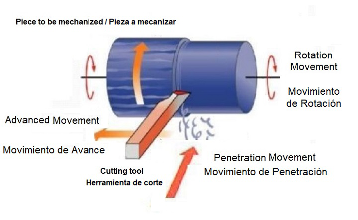
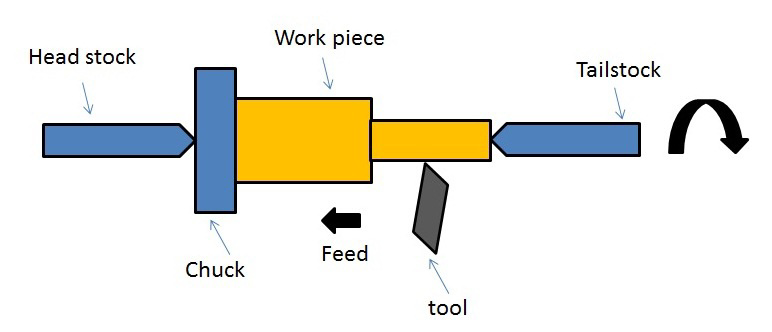
How would the ancients have powered this method of cutting a piece of stone?
Certainly in my experience , the speed that could be achieved by hand turning from a lever attached to the ‘chuck ‘ end (the drive end) coupled with a flywheel for torque would easily be enough for very effective turning.
There is also another method that we may all have seen in old millstones the world over for using a spindle to drive and turn a heavy stone- a square hole that provides the torque necessary to turn the stone - over here in England I have heard of this method referred to as “ dog drive” the square section being the ‘dog’ but it may have other names across the world .
Here is an example:

Let us now transport ourselves to Tanis , in the Nile delta- an old city of some importance , and as we can see from pictures and info, not excavated to its full potential , and most certainly used for quarrying etc over the millennia , as much of the AE sites were at some point .
Lying on the ground, many broken , and highly eroded , lay the remains of many of the ‘Palm Frond’ style of AE pillars.
Less eroded examples are to be seen elsewhere in Egypt and they are simply beautiful.
These marvels are one piece of Aswan red granite and can be over 15 metres in length , and must weigh in excess of 30 tonnes when complete. But I stand to be corrected on that.
Let’s just say they are insanely large, insanely heavy , and stunningly executed.
As we have seen from the diagrams above, the workpiece is suspended between two points, the ‘drive ‘ end on the left, and a drilled point on the right of the workpiece, we call this ‘centre drilling ‘ and it’s necessary to ensure stability of the workpiece and for the workpiece itself to ‘turn’ on this point ,which will allow you to achieve accuracy, and straight edges along the workpiece.
Here is an example of ‘dog drive’ cut in the top of these eroded pillars :
This would be the left side of the column if it were placed horizontally to be turned on a lathe type device .
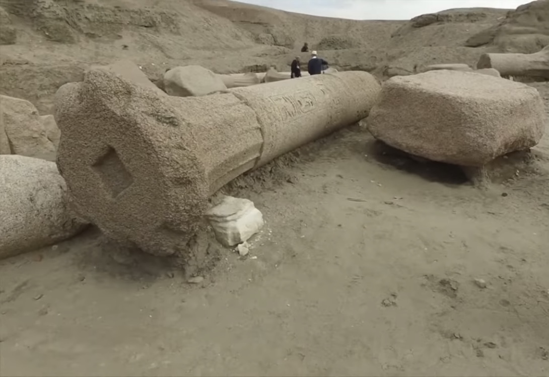
Here is the bottom face of a pillar, which it would stand on when upright, notice the ‘centre drill hole’ which would allow rotation freely and accurately in parallel with the ‘dog drive’

In this picture, notice how straight the top edge of the column is, even though there is erosion present ; this parallelism is an indication of ‘turning’ with a tool pulled from right to left along the column to produce this. Perhaps using a guide rail.
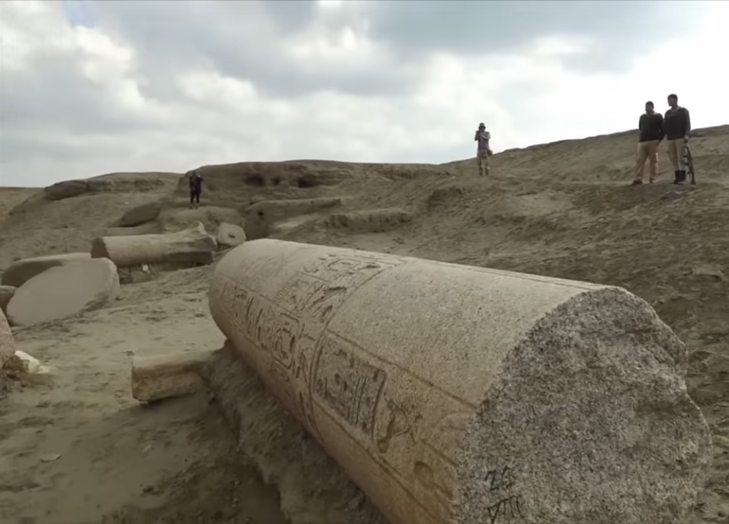
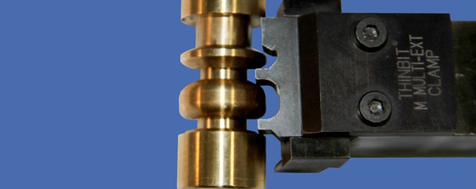
The next image is a classic example of what we call ‘form tooling ‘ - a tool that will have a shape to it, that will cut this shape into the workpiece as it spins towards you - these can be anything : V shapes , slits, convex shapes , and here, a concave form tool to produce these curved ridges , something along the lines of this:

I have wondered for a long time where the workshops were for such objects to be made , have any been found, and ARE Egyptologists Looking for the right thing ? Or even looking ?!
To make these columns horizontally , which in my opinion they were, and with a dog drive on the left , and the right hand centre point , we need to be looking for some raised platforms some 18 metres or so apart , where the column would be suspended between the two at a height that can be worked on by standing next to it, so around 5 foot perhaps in height , quite possibly .
Were these turned at the quarries? I don’t know; I’m more inclined to think that roughed blocks were taken somewhere more specialist to complete them .
There are many beautiful types of AE columns , all staggering in various designs AND complexity, but where were they made? Lots of temples, lots of columns.
Has anyone measured these columns for consistency.? ie, are they VERY similar in diameter , was there a ‘standard ‘ ?
I say this because the amazing palm frond design at the top of these columns is almost worthy of a thread on its own, engineering wise, but basically what has occurred here is called “dividing” in engineering , a commonly used technique where, In layman’s terms , one will take the diameter of the workpiece which is used to calculate the number of ‘faces’ you wish to put on the workpiece .
Here the palm fronds are a series of sectional divisions of the diameter figure .
There must have been a standard diameter to allow the correct amount of fronds , all equally spaced , in the design .
You can only obtain this effective division by knowing the diameter of your workpiece .
These people were GOOD at this .
I have showed these pictures to friends I have in the turning/engineering business , and without me giving my opinion first, I have asked many “ how do you think this was made ?”
Instantly the response is “ Lathe” .
Then they all say something along the lines of “ bloody obvious “.
I know it’s difficult for those who aren’t engineers to get your head around this technique , engineering terms, and visualising what I’m talking about , but I hope I’ve explained this position clearly enough.
I’ll clarify anything for anyone who doesn’t get what I’m talking about technically .
If the AE could quarry, move, cut granite , and FAR larger pieces than these, with such fluidity and ease, turning columns in this manner would be nothing to them .
Of course, the usual detractors will always chime In with the blanket statement “There were no lathes in ancient Egypt “ (Harte et al)
I have always disagreed with this position as I work on a lathe and a milling machine every day, for a living , also making tooling for each job if necessary , and have seen objects and tool marks on AE objects that I see at work every day, and that are the forensic signature of Lathework and turning.
A lathe is used in many ways , and will create for you perfectly round parts, cylinders , internally bored out cylinders , and many more shapes are possible by spinning the ‘workpiece’ horizontally, a tool is applied from a fixed position, and you can begin to cut your circular form , or cylinder etc etc
Before we start, the Lathe has had a wonderful evolution , from single hand powered turning , using a wooden pole connected to a rope to power the turning spindle through its flexing , Industrial Revolution belt drive , through to small electric motors , right through to todays insane multi-horsepower cnc lathes than can spin up incredible rpms.
I am NOT talking about a modern lathe , neither one powered by electricity.
Hand winding , using flywheels is a perfectly acceptable method for the time period I’m talking about - the Ancient Egyptians.
Here’s a couple of basic pictures that show how cutting a material on a lathe is done .


How would the ancients have powered this method of cutting a piece of stone?
Certainly in my experience , the speed that could be achieved by hand turning from a lever attached to the ‘chuck ‘ end (the drive end) coupled with a flywheel for torque would easily be enough for very effective turning.
There is also another method that we may all have seen in old millstones the world over for using a spindle to drive and turn a heavy stone- a square hole that provides the torque necessary to turn the stone - over here in England I have heard of this method referred to as “ dog drive” the square section being the ‘dog’ but it may have other names across the world .
Here is an example:

Let us now transport ourselves to Tanis , in the Nile delta- an old city of some importance , and as we can see from pictures and info, not excavated to its full potential , and most certainly used for quarrying etc over the millennia , as much of the AE sites were at some point .
Lying on the ground, many broken , and highly eroded , lay the remains of many of the ‘Palm Frond’ style of AE pillars.
Less eroded examples are to be seen elsewhere in Egypt and they are simply beautiful.
These marvels are one piece of Aswan red granite and can be over 15 metres in length , and must weigh in excess of 30 tonnes when complete. But I stand to be corrected on that.
Let’s just say they are insanely large, insanely heavy , and stunningly executed.
As we have seen from the diagrams above, the workpiece is suspended between two points, the ‘drive ‘ end on the left, and a drilled point on the right of the workpiece, we call this ‘centre drilling ‘ and it’s necessary to ensure stability of the workpiece and for the workpiece itself to ‘turn’ on this point ,which will allow you to achieve accuracy, and straight edges along the workpiece.
Here is an example of ‘dog drive’ cut in the top of these eroded pillars :
This would be the left side of the column if it were placed horizontally to be turned on a lathe type device .

Here is the bottom face of a pillar, which it would stand on when upright, notice the ‘centre drill hole’ which would allow rotation freely and accurately in parallel with the ‘dog drive’

In this picture, notice how straight the top edge of the column is, even though there is erosion present ; this parallelism is an indication of ‘turning’ with a tool pulled from right to left along the column to produce this. Perhaps using a guide rail.

The next image is a classic example of what we call ‘form tooling ‘ - a tool that will have a shape to it, that will cut this shape into the workpiece as it spins towards you - these can be anything : V shapes , slits, convex shapes , and here, a concave form tool to produce these curved ridges , something along the lines of this:


I have wondered for a long time where the workshops were for such objects to be made , have any been found, and ARE Egyptologists Looking for the right thing ? Or even looking ?!
To make these columns horizontally , which in my opinion they were, and with a dog drive on the left , and the right hand centre point , we need to be looking for some raised platforms some 18 metres or so apart , where the column would be suspended between the two at a height that can be worked on by standing next to it, so around 5 foot perhaps in height , quite possibly .
Were these turned at the quarries? I don’t know; I’m more inclined to think that roughed blocks were taken somewhere more specialist to complete them .
There are many beautiful types of AE columns , all staggering in various designs AND complexity, but where were they made? Lots of temples, lots of columns.
Has anyone measured these columns for consistency.? ie, are they VERY similar in diameter , was there a ‘standard ‘ ?
I say this because the amazing palm frond design at the top of these columns is almost worthy of a thread on its own, engineering wise, but basically what has occurred here is called “dividing” in engineering , a commonly used technique where, In layman’s terms , one will take the diameter of the workpiece which is used to calculate the number of ‘faces’ you wish to put on the workpiece .
Here the palm fronds are a series of sectional divisions of the diameter figure .
There must have been a standard diameter to allow the correct amount of fronds , all equally spaced , in the design .
You can only obtain this effective division by knowing the diameter of your workpiece .
These people were GOOD at this .
I have showed these pictures to friends I have in the turning/engineering business , and without me giving my opinion first, I have asked many “ how do you think this was made ?”
Instantly the response is “ Lathe” .
Then they all say something along the lines of “ bloody obvious “.
I know it’s difficult for those who aren’t engineers to get your head around this technique , engineering terms, and visualising what I’m talking about , but I hope I’ve explained this position clearly enough.
I’ll clarify anything for anyone who doesn’t get what I’m talking about technically .
If the AE could quarry, move, cut granite , and FAR larger pieces than these, with such fluidity and ease, turning columns in this manner would be nothing to them .
edit on 12-1-2023 by bluesfreak because: (no reason given)
originally posted by: bluesfreak
How would the ancients have powered this method of cutting a piece of stone?
Certainly in my experience , the speed that could be achieved by hand turning from a lever attached to the ‘chuck ‘ end (the drive end) coupled with a flywheel for torque would easily be enough for very effective turning.
By placing the peice to be lathed in the river, remember a block will only weigh maximum half as much in the water due to buoyancy/ displacement and then using the power of said river to turn the dog/ gear on both sides attached to block.
Not to mention the cooling effect for keeping tools cool for longevity.
The river itself is your lathe/ missing workshops.
Need more power- narrow down river for greater flow.
Enjoy.
edit on 12-1-2023 by CthruU because: (no reason given)
edit on 12-1-2023 by CthruU because: (no reason
given)
edit on 12-1-2023 by CthruU because: (no reason given)
edit on 12-1-2023 by CthruU because: (no reason
given)
a reply to: bluesfreak
Egyptian archeology has always fascinated me, and I LOVE your presentation! All of the standard theories have always felt like they really miss the mark, and the more they double down the more boring the documentaries have become for me.
Thanks for the new angle! Do you have any theories on the large stone spheres of Costa Rica? Their purpose, or how they were created?
Thanks for the Lathe 101 Class. I knew about wood and metal work on a lathe, but never thought about doing stone that way. Very well presented
information and you never lost me with your explanations, S&F.
edit on 12-1-2023 by MichiganSwampBuck because: Typo
a reply to: bluesfreak
This is incredible and I agree with you 100%, definitely lathes in Ancient Egypt.
Excellent thread mate, thanks for posting!
This is incredible and I agree with you 100%, definitely lathes in Ancient Egypt.
Excellent thread mate, thanks for posting!
a reply to: bluesfreak
Nice thread-You make a good case.
I have not heard the idea of the ancient Egyptians using this method-but there are some ancient temples in India which contain incredible pillars which are almost certainly made using the same technique.
Some of the more famous(and awesome) examples are found in the Hoysaleswara Temple.
Here is one-
obsballona.net...
Note the people in the right corner of the pic-That pillar must be a good few tons..Imagine the size of the lathe!
I wondered if they may have used some kind of water wheel contraption to spin the lathe?
Not sure about that though.
a reply to: bluesfreak
Thanks for the interesting read, this all makes sense.. and is most likely how they did those pillars.
Zero chance that modern archaeology or egyptology would even consider this as a possibility tho,
If this theory has not been taught in universities in the last decades then its pseudoscience.
Thanks for the interesting read, this all makes sense.. and is most likely how they did those pillars.
Zero chance that modern archaeology or egyptology would even consider this as a possibility tho,
If this theory has not been taught in universities in the last decades then its pseudoscience.
a reply to: bluesfreak
If you work on a lathe or milling machine every day, why didn't you immediately notice that the diagram is WRONG?
Every lathe I ever worked on, normally rotated COUNTERCLOCKWISE.
If you work on a lathe or milling machine every day, why didn't you immediately notice that the diagram is WRONG?
Every lathe I ever worked on, normally rotated COUNTERCLOCKWISE.
There is no doubt in my mind that those Hoysaleswara columns are lathe turned .
Beautiful beautiful work, an example of Lathe poetry to me..!
Wonderful.
a reply to: Silcone Synapse
Beautiful beautiful work, an example of Lathe poetry to me..!
Wonderful.
a reply to: Silcone Synapse
I did notice that once I’d posted it tbh, but couldn’t be bothered to change it .
Now , the top diagram is spinning away and would require the cutting face of the tool to be on the underside of the tool.
Common and modern usage is the bottom picture, spinning toward you , with the cutting face of the tool on the topside of the tool , thus obviously easier to see what you’re doing .
In the early days of the industrial revolution, it was common for both methods , and in Some cases a reverse tool post with the tool on the other side , but the bottom picture obviously became the modern standard .
every lathe I have ever worked on has spun TOWARD the operator , but it wasn’t always so in the history of turning .
I was just trying to find some simple pics for non engineers to understand the principle.
Sorry it offended you so much.
a reply to: JFredMuggs
edit on 12-1-2023 by bluesfreak because: (no reason given)
originally posted by: JFredMuggs
a reply to: bluesfreak
If you work on a lathe or milling machine every day, why didn't you immediately notice that the diagram is WRONG?
Every lathe I ever worked on, normally rotated COUNTERCLOCKWISE.
What difference does it make which way the lathe turns? The principle of the process is exactly the same...
Do you not see the chuck?
Was that an attempt to "debunk" the OP's observation?
edit on 1212023 by Wide-Eyes because: (no reason given)
originally posted by: Wide-Eyes
originally posted by: JFredMuggs
a reply to: bluesfreak
If you work on a lathe or milling machine every day, why didn't you immediately notice that the diagram is WRONG?
Every lathe I ever worked on, normally rotated COUNTERCLOCKWISE.
What difference does it make which way the lathe turns? The principle of the process is exactly the same...
Do you not see the chuck?
Was that an attempt to "debunk" the OP's observation?
No.
But IF one is posting something to "educate the masses", and to be used as a premise for an argument, should it not be CORRECT?
a reply to: bluesfreak
I've used many lathes and milling machines in my days working in a metal shop!
This is fascinating...that would be an enormous one for sure!
Some questions pop up...but nothing that would make this impossible...it certainly is plausible!
I've used many lathes and milling machines in my days working in a metal shop!
This is fascinating...that would be an enormous one for sure!
Some questions pop up...but nothing that would make this impossible...it certainly is plausible!
It is correct .
It can be done both ways ,
But yes, the bottom diagram is the method used today .
I have read of early French lathes around the Industrial Revolution using the top diagram method , but it probably fizzled out as one really wants to see the cutting face on the tool.
I notice that’s all you had to say on the thread . a reply to: JFredMuggs
originally posted by: JFredMuggs
a reply to: bluesfreak
If you work on a lathe or milling machine every day, why didn't you immediately notice that the diagram is WRONG?
Every lathe I ever worked on, normally rotated COUNTERCLOCKWISE.
Haha...what?
Everyday huh? I doubt that...every modern lathe runs in both directions...I have one in my garage right now that runs both ways (got it from Harbor Freight)!
Also...depending on which side of the lathe you were standing on...it could be clockwise or counterclockwise!
As long as the rotation is against the cutting tool...it doesn't much matter. Although to polish things I often run mine in both directions to eliminate "scoring" before I blue something for instance!
Your proposed "COUNTERCLOCKWISE" argument is invalid! Sorry to break it to you Mr. Machinist!
By the way...lathes and milling machines are two different things...hence they have different names!
originally posted by: bluesfreak
Just be careful of that Chuck flying off at high speed when running your lathe in reverse !
I’ve seen one fly across the room right past the operators head when it hadn’t all been checked correctly for reverse turning.
Scary as hell!!!!!
a reply to: jerryznv
Here is my thought on that...
Today we tighten a chuck down using threads and a chuck key...in ancient times it more than likely was wedges or something similar.
Yes though...on my own lathe I have chucks that tighten in both directions (actually mine is pretty fancy and I can change the chuck out pretty quickly).
Yes...safety first...always!
new topics
-
This is an interesting picture. Do we actually pick our leaders?
Politicians & People: 3 hours ago -
U.S. Govt Agencies That Protect Criminals in Government - National Archives Records Admin-NARA.
Political Conspiracies: 4 hours ago -
Trump says ownership of Greenland 'is an absolute necessity'
Other Current Events: 6 hours ago -
An Updated China Navy Analysis and the Challenges of their AI/Drone Development
Military Projects: 7 hours ago -
University looking for gender diverse kids to play with transgender dolls for research
Social Issues and Civil Unrest: 7 hours ago -
FAA Investigates Christmas Drone Show Gone Wrong in Orlando, FL 12/2024
Other Current Events: 7 hours ago
top topics
-
University looking for gender diverse kids to play with transgender dolls for research
Social Issues and Civil Unrest: 7 hours ago, 9 flags -
This is an interesting picture. Do we actually pick our leaders?
Politicians & People: 3 hours ago, 8 flags -
RIP Merrily Harpur British Big Cat Realist
Cryptozoology: 16 hours ago, 7 flags -
Trump says ownership of Greenland 'is an absolute necessity'
Other Current Events: 6 hours ago, 6 flags -
U.S. Govt Agencies That Protect Criminals in Government - National Archives Records Admin-NARA.
Political Conspiracies: 4 hours ago, 5 flags -
Can we be certain that Jesus Christ was born on December 25th?
Religion, Faith, And Theology: 14 hours ago, 4 flags -
Mass Extinctions May Hold the Key to Life in the Universe
Education and Media: 12 hours ago, 4 flags -
FAA Investigates Christmas Drone Show Gone Wrong in Orlando, FL 12/2024
Other Current Events: 7 hours ago, 4 flags -
An Updated China Navy Analysis and the Challenges of their AI/Drone Development
Military Projects: 7 hours ago, 3 flags
active topics
-
President-elect TRUMP Picks MATT GAETZ for his ATTORNEY GENERAL - High Level PANIC Ensues.
2024 Elections • 135 • : fringeofthefringe -
‘Something horrible’: Somerset pit reveals bronze age cannibalism
Ancient & Lost Civilizations • 20 • : ToneD -
Panamanian President-“every square meter” of the Panama Canal belongs to Panama.
New World Order • 34 • : fringeofthefringe -
Can we be certain that Jesus Christ was born on December 25th?
Religion, Faith, And Theology • 29 • : visitedbythem -
This is an interesting picture. Do we actually pick our leaders?
Politicians & People • 5 • : rickymouse -
Trump says ownership of Greenland 'is an absolute necessity'
Other Current Events • 20 • : fringeofthefringe -
University looking for gender diverse kids to play with transgender dolls for research
Social Issues and Civil Unrest • 22 • : NorthOS -
$100's of Billions For Student Loan Relief Meanwhile This...
US Political Madness • 16 • : WeMustCare -
Biden Nationalizes Another 50,000+ Student Loans as He Heads for the Exit
US Political Madness • 20 • : WeMustCare -
Why isn't Psychiatry involved?
Social Issues and Civil Unrest • 35 • : lilzazz
