It looks like you're using an Ad Blocker.
Please white-list or disable AboveTopSecret.com in your ad-blocking tool.
Thank you.
Some features of ATS will be disabled while you continue to use an ad-blocker.

Tri-Mag DC Motor (theoretical)
page: 11
share:
This is a concept for a DC motor which I came up with at least 5 years ago now. Well I've tweaked it a little bit since then but it's close to the
original. I've held off showing anyone this design in the hopes that I might be able to patent it or something, but then I realized I'm never going to
get around to that. So I may as well share this in case it is something we haven't thought of before. I looked around a few patent databases and
couldn't find anything similar, but I'm clearly no expert at finding patents.
Don't get me wrong, I will still take action if I find anyone trying to steal this idea and use it without my permission (assuming it isn't already the intellectual property of someone else). Let this post and the date-time stamp be a proof of when I first presented this idea publicly. ATS may be an odd place to post something like this, but we have a lot of great minds here who are very knowledgeable when it comes to science and physics, not to mention this is one of the few forums I visit which has a science section.
So without further blab, here is the schematic:
When I first started to design a DC electric motor the first thing I did was think about the ideal properties of an electric motor. Following the right-hand-thumb-rule or what ever they call it, we can determine the nature and strength of the forces generated when we place a wire with flowing current near a magnet. One of the most efficient ways to maximize the force generated when you place a magnet near flowing current is to twist the wire into a coil shape, so that is how I tried to design my motor.
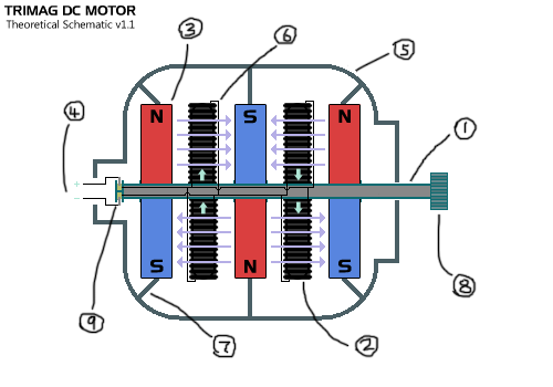
The blue arrows in the diagram represent the direction of the magnetic field, and the green arrows represent the direction of the electric current / flow of electrons through the wire. The current flows through the coils from the terminals and they are set up in a parallel circuit so each coil gets the same amount of current. If you implement the right-hand-thumb-rule on this diagram you should find that each coil in the top row is pushed in an opposite direction from the ones below them, causing a rotation. The commutator keeps it going.
It is fairly simple design but it's unusual compared to most diagrams of a DC motor. The simple yet novel design follows the most important rules in a neat way. My thought is that this type of design would probably produce a lot of torque and would be best suited to heavy duty uses where large permanent magnets are used. I call it the "Tri-Mag" DC Motor because it has 3 permanent magnets but really you could add more magnets and coils. It should get exponentially more efficient with more magnets.
NOTE: The wires are shown exiting the coils and travelling into the shaft to the side of the coil. This is mainly for demonstrational purposes as it would seem more practical to send the wire back down the center of the coil, especially if we made the core from something which will insulate the wire from magnetic fields, because after all it is travelling in the opposite direction and will create a force which will act against the desired motion of the coil.
Don't get me wrong, I will still take action if I find anyone trying to steal this idea and use it without my permission (assuming it isn't already the intellectual property of someone else). Let this post and the date-time stamp be a proof of when I first presented this idea publicly. ATS may be an odd place to post something like this, but we have a lot of great minds here who are very knowledgeable when it comes to science and physics, not to mention this is one of the few forums I visit which has a science section.
So without further blab, here is the schematic:
- The hollow shaft / rotor (the black lines inside it are wires).
- Coils wrapped around what might be called stators (attached to the rotor).
- Permanent magnets, the rotor goes through holes in these magnets.
- The positive and negative battery terminals / inputs.
- Some sort of light and durable metal or plastic casing / mounting.
- Wires coming from the top of the coils and returning into the shaft.
- This is where the magnets are fastened securely to the casing.
- Load bearing end of the shaft / rotor (a cog attached in this case).
- The commutator, ideally some sort of fancy brushless solution.
When I first started to design a DC electric motor the first thing I did was think about the ideal properties of an electric motor. Following the right-hand-thumb-rule or what ever they call it, we can determine the nature and strength of the forces generated when we place a wire with flowing current near a magnet. One of the most efficient ways to maximize the force generated when you place a magnet near flowing current is to twist the wire into a coil shape, so that is how I tried to design my motor.
The blue arrows in the diagram represent the direction of the magnetic field, and the green arrows represent the direction of the electric current / flow of electrons through the wire. The current flows through the coils from the terminals and they are set up in a parallel circuit so each coil gets the same amount of current. If you implement the right-hand-thumb-rule on this diagram you should find that each coil in the top row is pushed in an opposite direction from the ones below them, causing a rotation. The commutator keeps it going.
It is fairly simple design but it's unusual compared to most diagrams of a DC motor. The simple yet novel design follows the most important rules in a neat way. My thought is that this type of design would probably produce a lot of torque and would be best suited to heavy duty uses where large permanent magnets are used. I call it the "Tri-Mag" DC Motor because it has 3 permanent magnets but really you could add more magnets and coils. It should get exponentially more efficient with more magnets.
NOTE: The wires are shown exiting the coils and travelling into the shaft to the side of the coil. This is mainly for demonstrational purposes as it would seem more practical to send the wire back down the center of the coil, especially if we made the core from something which will insulate the wire from magnetic fields, because after all it is travelling in the opposite direction and will create a force which will act against the desired motion of the coil.
edit on 25/1/2013 by ChaoticOrder because: (no reason given)
I am not an electrical expert, elementary at best. it seems plausible. I guess the more winding of copper, and the more powerful the magnet, may
generate more power. am i right to say that. I dont know, like i said No expert, just like to see what other people are up to, and play with my own
designs. Good Job keep up the good work, we need more minds that enjoy to create and harness energy. I enjoy dabbeling in the free energy designs, and
have multiple designs for using parabolic mirrors, using different curves to come up with the best reflections from the sun. also I play around with
different materials for the reflection Silver is good, but I think Germaniam may be a better reflector, just expensive. I bend glass for a living.
Hence my name
reply to post by Glassbender777
It's plausible at worste. It should certainly work according to everything I know about physics, and I know enough. The only reason I label it as "theoretical" is because I haven't actually built one and tested it. I'm 98% sure it works though.
Well sure, stronger/bigger magnets and larger coils is always going to make a more powerful motor. That's just scaling up the design.
I've dabbled with a few so called free energy devices but this is certainly not one of them. It's just a plain old DC motor without any magical abilities as far as I know.
it seems plausible.
It's plausible at worste. It should certainly work according to everything I know about physics, and I know enough. The only reason I label it as "theoretical" is because I haven't actually built one and tested it. I'm 98% sure it works though.
I guess the more winding of copper, and the more powerful the magnet, may generate more power. am i right to say that.
Well sure, stronger/bigger magnets and larger coils is always going to make a more powerful motor. That's just scaling up the design.
I enjoy dabbeling in the free energy designs, and have multiple designs for using parabolic mirrors, using different curves to come up with the best reflections from the sun.
I've dabbled with a few so called free energy devices but this is certainly not one of them. It's just a plain old DC motor without any magical abilities as far as I know.
edit on 25/1/2013 by ChaoticOrder because: fixed stupid mistake
reply to post by ChaoticOrder
It's good to see original research debut on ATS. I know nothing about this, but you seem to believe it is a good discovery and have brought it forward, which is 62.5% of the way to success! Nice work.
It's good to see original research debut on ATS. I know nothing about this, but you seem to believe it is a good discovery and have brought it forward, which is 62.5% of the way to success! Nice work.
Originally posted by Aleister
reply to post by ChaoticOrder
It's good to see original research debut on ATS. I know nothing about this, but you seem to believe it is a good discovery and have brought it forward, which is 62.5% of the way to success! Nice work.
lol well if I really wanted to head down the path of success I should have refrained from posting this on ATS and find out if I can get it patented. I still might, but I currently lack the funds. Need investors. Wink wink.
edit on 25/1/2013 by ChaoticOrder because: (no reason
given)
The layout resembles an axial gap motor we designed years ago for a fuel cell company. Well actually, it looks like 2-and-a-half of them sandwiched
together. If it's going to be brushless DC, then the magnets need to be the "spinning" part, not the coils.
Also, I think the magnetization in the magnets (they're disks, right?) would need to be oriented with north/south on the sides facing the coils, not on opposite ends like the picture shows.
I'm kind of shooting from the hip here, I design the mechanicals not the magnetics, but I do know how the magnetic poles want to be positioned relative to the coils, and when I look at the picture it doesn't look right. The magnets are labeled like radial gap motor magnets, and the picture is clearly an axial gap design.
Also, the coils in axial gap motors aren't typically "toroidal" as seen in the picture, they're more like a "god's eye" if you're familiar with what that is.
One thing is for sure, electric motor design is a finicky thing with tons of variables that I wouldn't even pretend to grasp.
edit on 25-1-2013
by tjack because: (no reason given)
Originally posted by ChaoticOrder
The blue arrows in the diagram represent the direction of the magnetic field, and the green arrows represent the direction of the electric current / flow of electrons through the wire. The current flows through the coils from the terminals and they are set up in a parallel circuit so each coil gets the same amount of current. If you implement the right-hand-thumb-rule on this diagram you should find that each coil in the top row is pushed in an opposite direction from the ones below them, causing a rotation. The commutator keeps it going.
Maybe your drawing is misleading me, but the green arrows would be showing the direction of the magnetic field, not the current. The current would be spiraling down in a more or less horizontal orientation. Also see this image:
I think you are making the same mistake with the magnets. See:
Note that both images are flipped 90 degrees compared to the magnets/solenoids in your drawing.
edit on 25-1-2013 by -PLB- because: (no reason
given)
reply to post by -PLB-
The current flows trough the coil as if it were a single wire. And the magnetic field does travel from pole to pole but with two or more magnets close to each other the main strength of the field is travelling between the two poles of each magnet. If you don't understand the physics you shouldn't comment.
The current flows trough the coil as if it were a single wire. And the magnetic field does travel from pole to pole but with two or more magnets close to each other the main strength of the field is travelling between the two poles of each magnet. If you don't understand the physics you shouldn't comment.
reply to post by ChaoticOrder
Oohkeee, nice and friendly reply. I will leave you with your little crappy toy, its not like I care if it really works or not.
Oohkeee, nice and friendly reply. I will leave you with your little crappy toy, its not like I care if it really works or not.
Where do the back-irons go? Every electric motor I've been involved with so far has a "back-iron" on the opposite side of the magnet relative to
the air gap. It has something to do with the flux circuit and I think it's an important part in the design, if a motor is to be efficient.
The magnet in the center would probably want a back-iron on both sides, which would pretty much negate it's participation in the design. I think the center magnet would actually need to be 2 magnets sandwiched around a double-thickness back-iron, in order for the flux circuit to exist going both ways into the coils they lie between.
There's also typically a stack of silicon steel laminations that the coils are wound around (in radial gap motors) or live in front of (in axial gap motors), which are not represented in your layout.
I hope I don't come across as trying to shoot down your design, it's interesting to me, I'm just throwing out the admittedly little knowledge I have about electric motors after having designed the mechanics of them going on ten years now, but that experience is based on traditional motor physics, not brave new theoretical possibilities.
Keep running with it, you may have discovered something new! Won't know until you build and test one though.
new topics
-
COMPILATION: The Science of Ghosts and Ghost Hunting Why Files
Paranormal Studies: 2 hours ago -
Raytheon fined 950 million for defrauding the Pentagon
History: 4 hours ago -
Federal Government and Auditors Warn States Dominion Election Systems are Easy to Hack.
2024 Elections: 8 hours ago -
Breaking! Kamala Family Friend Confirms Race Hoax
US Political Madness: 10 hours ago
top topics
-
Breaking! Kamala Family Friend Confirms Race Hoax
US Political Madness: 10 hours ago, 24 flags -
Uk Govt sending staff and recruiting for people to campaign for Harris in the US
2024 Elections: 13 hours ago, 13 flags -
Candidate DONALD TRUMP Answering Questions from HISPANIC voters at Univision Town Hall 10-2024.
2024 Elections: 16 hours ago, 8 flags -
Scientists created a human-lamb hybrid in 1997 and I have questions
General Chit Chat: 17 hours ago, 7 flags -
Federal Government and Auditors Warn States Dominion Election Systems are Easy to Hack.
2024 Elections: 8 hours ago, 6 flags -
Toxoplasma Gondii Defib The Cat And The Kiffness
Pets: 16 hours ago, 5 flags -
Raytheon fined 950 million for defrauding the Pentagon
History: 4 hours ago, 3 flags -
COMPILATION: The Science of Ghosts and Ghost Hunting Why Files
Paranormal Studies: 2 hours ago, 2 flags
active topics
-
The evil government is behind Helene (proof online government document)
Geo-Engineering and Chemtrails • 119 • : ADVISOR -
Uk Govt sending staff and recruiting for people to campaign for Harris in the US
2024 Elections • 27 • : SprocketUK -
How Communism and Marxism Were Introduced in the USA
New World Order • 140 • : Kurokage -
Federal Government and Auditors Warn States Dominion Election Systems are Easy to Hack.
2024 Elections • 9 • : JJproductions -
Conspiracies and Neurotiscism
Philosophy and Metaphysics • 36 • : whereislogic -
Boy 7 Dies And 6 In Hospital After Devastating Explosion Destroys House In Newcastle
Mainstream News • 33 • : bastion -
COMPILATION: The Science of Ghosts and Ghost Hunting Why Files
Paranormal Studies • 0 • : 727Sky -
Breaking! Kamala Family Friend Confirms Race Hoax
US Political Madness • 54 • : Freeborn -
Keanu Reeves and Graham Hancock!
Ancient & Lost Civilizations • 10 • : sapien1982 -
Abortion Funds Are In ‘A State Of Emergency’
US Political Madness • 109 • : KrustyKrab
1